top of page

What is Flow Diagnostics?
Flow diagnostics is the science of measuring and quantifying a fluid flow (whether gas or liquid).
This may involve measuring variables of flow such as: velocity, density, pressure, temperature, species etc.
Whereas traditional flow measurement used to involve sticking a physical thermometer or pitot tube into the flow, modern flow diagnostics are based on optics (i.e. looking at the flow with a camera).
The modern method is non-invasive compared to physical probes, and provide high-dimensional data (e.g. a camera's 2D image compared to a probe point-measurement).
We are primarily interested in a subset of flow diagnostics called Particle Image Velocimetry (PIV) and Particle Tracking Velocimetry (PTV) which uses particles suspended in the flow to track local flow velocities.
A camera system aimed at the particles can measure the flow's velocity field (even 3D ones):
Problem with Existing Flow Diagnostics?

Using PIV / PTV as prime example:
One camera is required to measure 2D, 2 component (2C) flow velocity field.
Two cameras for 2D-3C velocity field with u,v,w velocity vectors.
Four cameras for 3D-3C velocity field (the current standard).
Six cameras or more for cutting-edge multi-physics measurements such as combustion or flow-structure interaction experiments.
This is not sustainable from the perspective of:
-
Cost
-
Experimental complexity
-
Optical access to subject
-
Risk of accidental misalignment
To mitigate these short-comings, we introduce a new class of imaging solution called "light-field (LF) flow diagnostics" that can achieve 3D velocity-field with as few as one camera.
Intro to LF Flow Diagnostics
A light-field (or "field of light rays") is a conceptual way of describing light in a 3D space.
The 3D space is assumed to be flooded with arbitrarily many light rays. E.g. a point object can give off infinitely many rays in radial directions.
A ray has position and orientation. This is usually described in terms of where the ray passes through two reference planes in space. E.g. (s,t) and (u,v) planes located at some (x,y,z) coordinates.
If the position + angle of two or more rays from an object is known, we can triangulate to the object's 3D position. When there are only two rays, this is the basic parallax / stereo-vision problem. In LF imaging, we typically deal with many more than two rays. More rays = more complex description of the LF = more accuracy.
LF flow diagnostics measures 3D flow velocity field by capturing the LF of particles suspended in the flow, and triangulating the positions of those particles (like 3D PIV).
Question: If having the LF allows for 3D flow diagnostics, how do I capture LF? With just one camera?

LF-Capturing Camera Systems
1 HydraEye

Designed by Prof. Tan Z. P. at Auburn University, the HydraEye is a canonical "quad-scope" or "view-splitter" camera system.
Prisms view-splitter on the center of the camera splits the main-lens' field-of-view (FOV) into four parts that are directed radially outward.
The four views are re-aimed onto a subject using four reflectors on arms.
HydraEye's creation was funded under the U.S. DURIP program with Prof. Vrishank Raghav. The camera system captures a small portion of the complete LF (i.e. only four independent perspectives/rays from an infinite set), providing it with sufficient information to perform 3D-PIV on the scale of 10-30cm.
HydraEye has so far been used on measuring 3D rotor flow on a 15cm coaxial rotor system. Data processed with LaVision Davis' tomo-PIV and Shake-the-Box. Results presented by Lokesh Silwal, Tan Z. P. and Raghav V. at AIAA SciTech 2021.

2 DragonEye v3

Designed by Prof. Tan Z. P. at Auburn University and continuously developed at ASARe Lab, the DragonEye is a novel plenoptic camera system.
Unlike regular cameras, plenoptic imagers contain a microlens array (MLA) with ~1million microscopic lenses in its imaging path. The MLA separates in-coming rays according to their angle (u,v), allowing both spatial (s,t) and angular (u,v) information to be preserved on the collected image.
DragonEye samples about 100 rays from every object's LF, allowing 3D triangulation with a very large degree of redundancy, AND allowing "fancy" computational tricks to be performed, such as altering the photo's perspective and focal-point after capture.

Examples of computational photography and 3D flow measurement using a single DragonEye:
LF-FSI
Fluid-structure interactions (FSI) is the next bastion of fluid dynamic research. Unlike tradition fluid dynamics where boundary conditions are fixed, FSI problems consider a dynamic and possible soft object in the flow. In FSI, structural dynamic of the subject and its subsequent fluid dynamics are tightly coupled physics that cannot be solved in isolation.
Modern FSI problems include:
-
Flexible leaflets in implanted heart-valves
-
Bio-mimicking soft robots
-
Flexing of wind turbine blades
-
Vibration of thin panels on hypersonic aircraft
Challenge and opportunity: The list of FSI problems is growing, but they lack a viable experimental method to test and measure FSI behaviors.

As highlighted above, the root of the challenge is the "curse of camera count" : more complex measurements need more cameras to capture all relevant information.
Current FSI experiments involve upwards to 6 cameras (4 for tomo-PIV + 2 for stereo-DIC).
Our goal: Is the achieve the most complex case of fully 3D, time-resolved FSI measurement with a single LF camera ("LF-FSI").
How LF-FSI work:
-
A subject is marked with surface-dots (e.g. a flapping wing).
-
Surrounding flow is seeded with PIV particles.
-
A single DragonEye captures dots and particles simultaneously.
-
A segmentation algorithm picks out these dots/particles from image and classify them into either surface or flow. (Here, the LF camera's ~100 redundant perspective-views come in handy!)
-
3D tracking is performed on the dots to capture surface behavior.
-
3D tracking/PIV is performed on particles to capture flow behavior.
-
Both results are combined for FSI data.


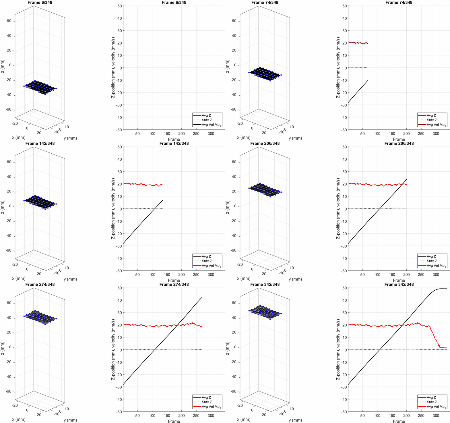
Demo results: surface moved at known velocity and tracked by DragonEye.
-
Error as low as 1% of full depth.
-
Correct velocity captured (with some jitter that can be cleared by filtering).
Experiments performed by Tan Z. P. at Auburn U.


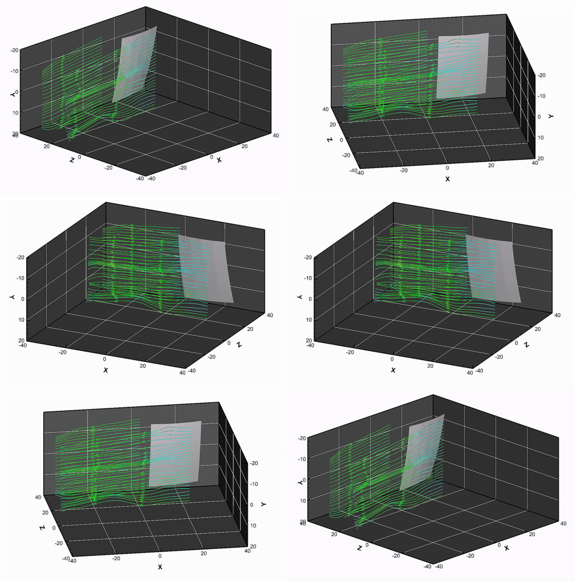
Demo results: simultaneous surface+flow measurement around a static/flapping wing via single DragonEye.
-
Demo of feasibility.
-
Large displacement measurement.


What's Next : Development DragonEye v4 and Next Iteration of FSI Procedure at ASARe Lab under Taiwan MOST grant.
+ Higher resolution
+ Higher temporal resolution
+ Lower cost
+ Higher robustness
bottom of page


